« Saturday

- IMG 5917
- IMG 5945
- IMG 4096
- IMG 4055
- IMG 5884
- IMG 5890
- IMG 5892
- IMG 0850
- IMG 5888
- IMG 4095
- IMG 4086
- IMG 5940
- IMG 4092
- IMG 4064
- IMG 5946
- 114 1494
- IMG 5881
- IMG 4094
- IMG 5914
- IMG 5883
- IMG 1444
- 2015-01-25 020
- IMG 4099
- IMG 0869
- IMG 5874
- IMG 0871
- IMG 5910
- IMG 1427
- 114 1488
- IMG 5865
- IMG 0872
- 2015-02-01 004
- IMG 4057
- 2015-01-25 015
- IMG 0873
- IMG 5938
- IMG 4054
- IMG 5939
- 114 1490
- IMG 4072
- IMG 5882
- IMG 4091
- IMG 4080
- IMG 5943
- IMG 4101
- IMG 4102
- IMG 5935
- IMG 5876
- IMG 5880
- 114 1487
- IMG 1430
- IMG 5915
- IMG 5934
- IMG 5891
- IMG 5923
- IMG 1429
- 114 1492
- IMG 5919
- IMG 5944
- 2015-01-25 014
- IMG 4056
- 2015-01-25 021
- IMG 5854
- IMG 4088
- IMG 4078
- 2015-01-25 002
- IMG 4087
- IMG 4070
- IMG 5936
- 114 1493
- IMG 5875
- IMG 5909
- 2015-02-01 003
- IMG 5869
- grbl
The grbl controller; underneath this stepper driver is an Arduino Uno and a breakout board. - IMG 5924
- IMG 4058
- IMG 0870
- IMG 1425
- IMG 5873
- 114 1486
- 2015-02-01 005
- IMG 1447
- IMG 1446
- IMG 5871
- IMG 4071
- IMG 1433
- IMG 5853
- IMG 5921
- IMG 1443
- 114 1491
- IMG 1441
- IMG 5860
- IMG 1448
- IMG 5922
- IMG 1445
- 2015-01-25 003
- IMG 1423
- IMG 4081
- 2015-02-01 006
- IMG 4097
- IMG 5937
- IMG 5928
- IMG 1438
- 2015-01-25 004
- IMG 5859
- IMG 1431
- IMG 5862
- IMG 5879
- IMG 5904
- IMG 4093
- 2015-02-01 008
- IMG 5907
- 2015-01-25 013
- 2015-01-25 006
- IMG 5925
- IMG 1440
- IMG 5931
- 2015-02-01 007
- 2015-01-25 005
- IMG 1422
- IMG 5933
- 2015-01-25 001
- 2015-01-25 010
- IMG 1421
- IMG 4077
- IMG 5926
- 2015-01-25 009
- 2015-02-01 010
- IMG 1432
- IMG 5932
- 2015-01-25 007
- 2015-02-01 009
- 2015-01-25 012
- IMG 5927
- 2015-01-25 011
 41176958-EFF3-49C6-8004-A401AC0F95F8
 IMG 5872
 P7220208
OLYMPUS DIGITAL CAMERA P7220178
OLYMPUS DIGITAL CAMERA P7220172
OLYMPUS DIGITAL CAMERA P7220133
OLYMPUS DIGITAL CAMERA P7220173
OLYMPUS DIGITAL CAMERA P7220171
OLYMPUS DIGITAL CAMERA P7220134
OLYMPUS DIGITAL CAMERA P7220079
OLYMPUS DIGITAL CAMERA P7220156
OLYMPUS DIGITAL CAMERA P7220169
OLYMPUS DIGITAL CAMERA P7220080
OLYMPUS DIGITAL CAMERA P7220089
OLYMPUS DIGITAL CAMERA P7220061
OLYMPUS DIGITAL CAMERA P7220060
OLYMPUS DIGITAL CAMERA P7220081
OLYMPUS DIGITAL CAMERA P7220082
OLYMPUS DIGITAL CAMERA P7220084
OLYMPUS DIGITAL CAMERA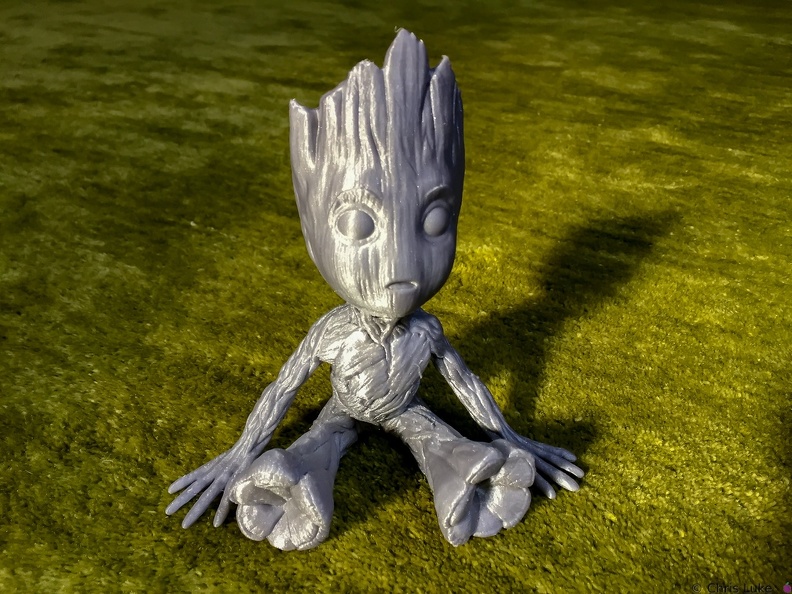 Baby Groot
 3C2A4856
 3C2A4323
 3C2A4771
 3C2A4324
 3C2A4590
 3C2A4322
 3C2A4663
 3C2A4821
 3C2A4314
 3C2A4317
 3C2A4307
 3C2A4305
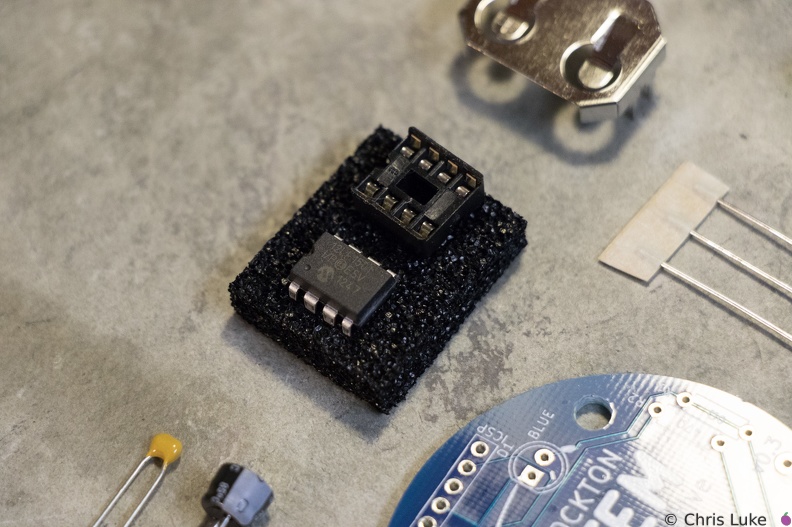 Stockton STEM Badge microcontroller
The chip is an inexpensive "PIC" microcontroller; this runs a program that controls the LEDs.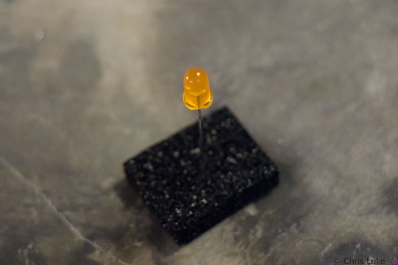 Stockton STEM Badge LEDs
LEDs have a flat edge on one side of their case.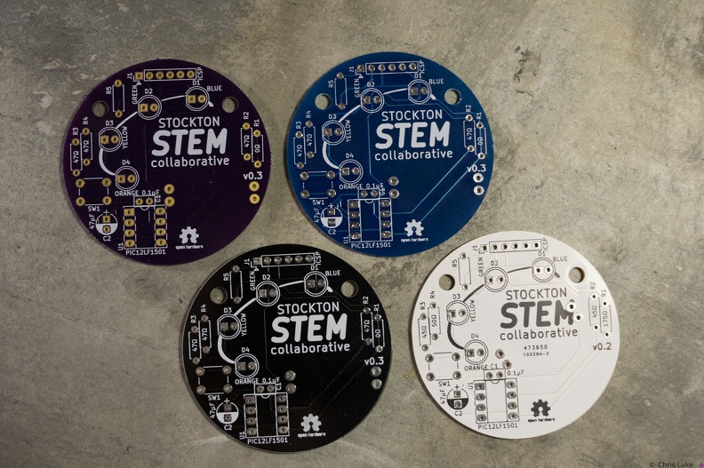 Stockton STEM Badge boards
The badge printed circuit board (PCB) comes in several colors.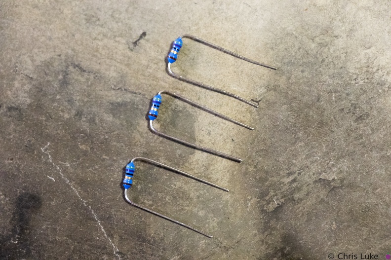 Stockton STEM Badge resistor legs
The resistor legs need to be bent in order to insert them into the board.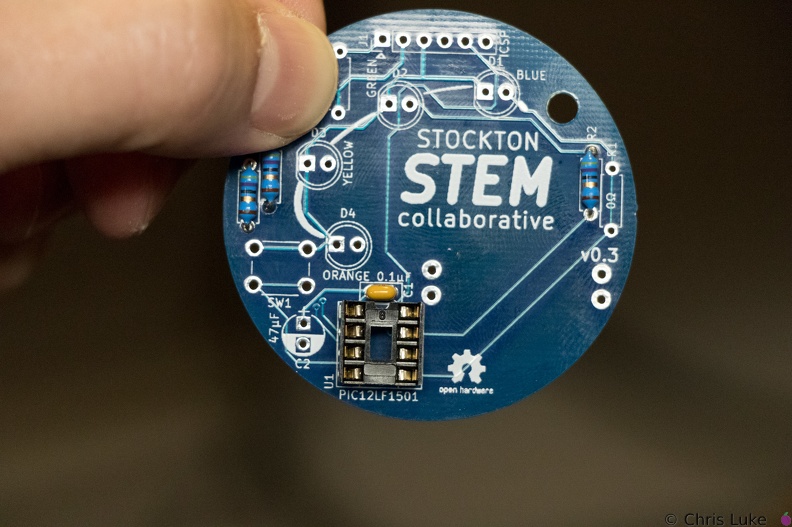 Stockton STEM Badge IC socket
Note the orientation of the indent at the upper edge of the IC socket.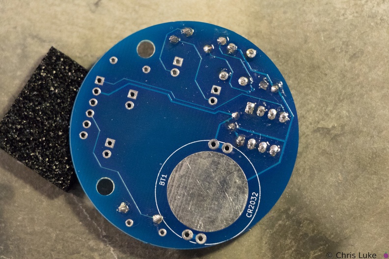 Stockton STEM Badge button
As with the IC socket, soldering one leg first and verifying component alignment will help prevent easy mistakes.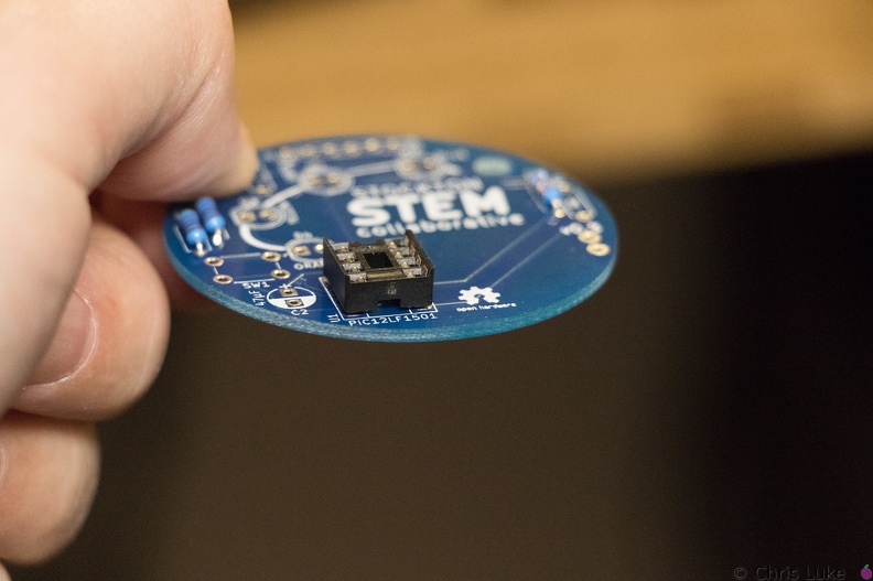 Stockton STEM Badge IC socket
The IC socket should lay flat against the board.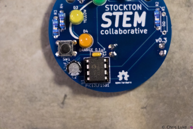 Stockton STEM Badge IC
Make sure the IC is correctly aligned before pushing it in.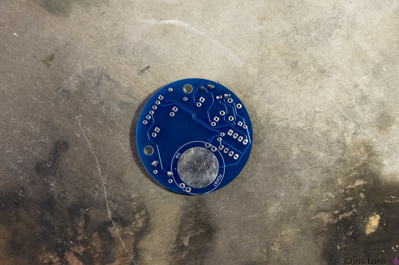 Stockton STEM Badge resistor legs
The legs are trimmed, the excess removed with side-cutters.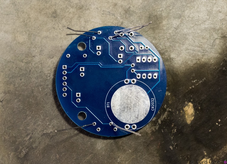 Stockton STEM Badge resistor legs
The legs are passed through the board holes; they may need pulling firmly, but not too firmly, with pliers to pull the resistor body flush with the board.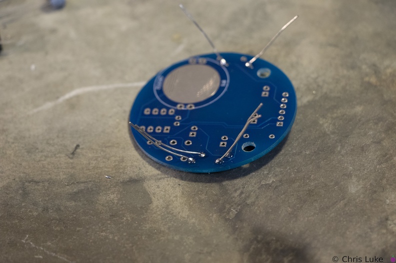 Stockton STEM Badge resistor legs
Soldered legs; only a small amount of solder is needed and it heat should be applied only briefly.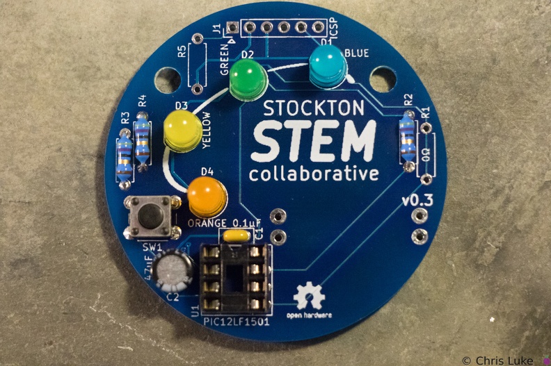 Stockton STEM Badge LEDs
All the LEDs have been soldered. Notice that they all have the same orientation; the flat edge is to the left.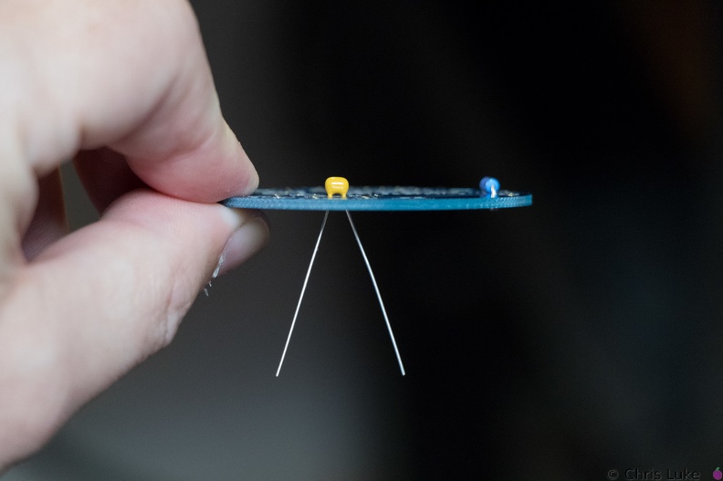 Stockton STEM Badge decoupling capacitor
This ceramic capacitor is not orientation sensitive. Decoupling means it absorbs electrical noise and is used to filter the power feeding the microcontroller.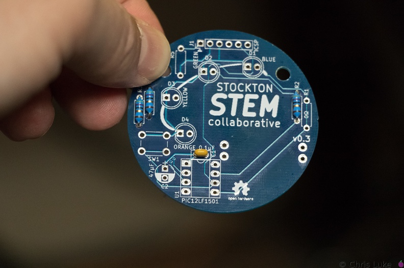 Stockton STEM Badge decoupling capacitor
The capacitor should sit flush with the board.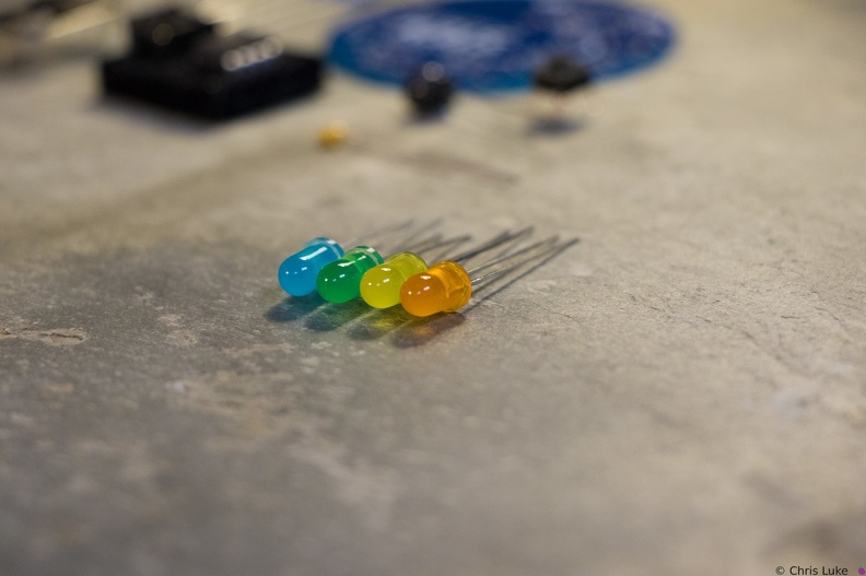 Stockton STEM Badge LEDs
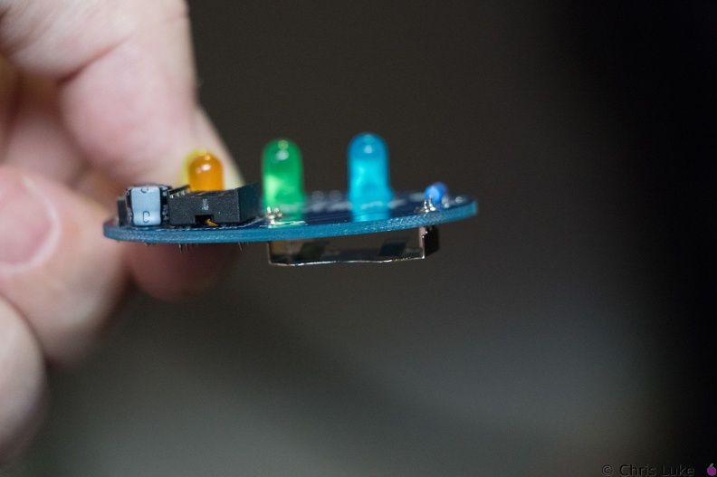 Stockton STEM Badge battery
It is possible for the holder to become hot during soldering; be careful when handling immediately after soldering.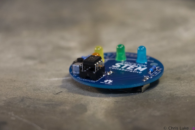 Stockton STEM Badge IC
When inserting the IC, firm but controlled pressure is needed to avoid bending the pins.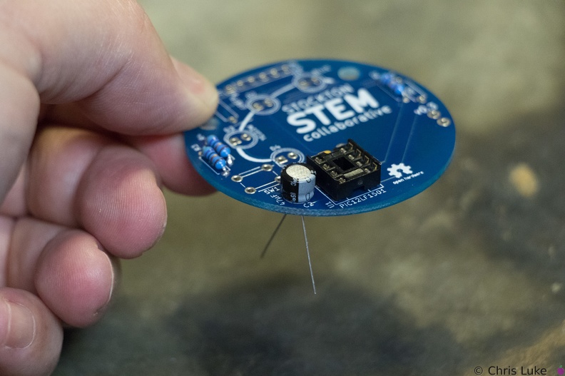 Stockton STEM Badge electrolytic capacitor
Orientation of this capacitor is important. There is a "+" symbol in the footprint of the component printed on the board; the "-" of the capacitor should be on the opposite side.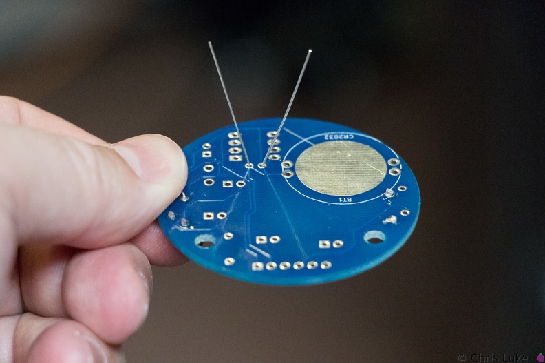 Stockton STEM Badge decoupling capacitor
As with the resistors, the legs should be splayed a little to help hold it in place for soldering.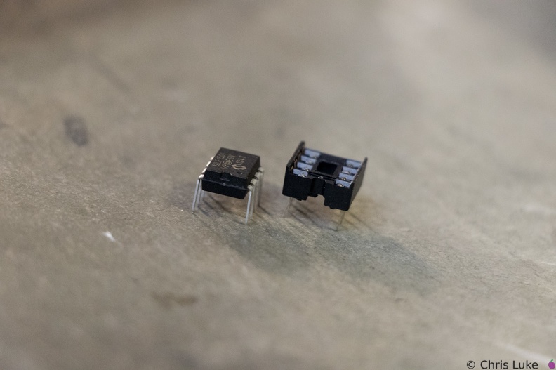 Stockton STEM Badge IC and socket
The legs of the chip need to be straight otherwise they will not properly insert into their positions in the socket. It is easy to bend or break the legs if care is not taken.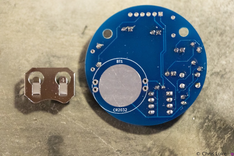 Stockton STEM Badge battery
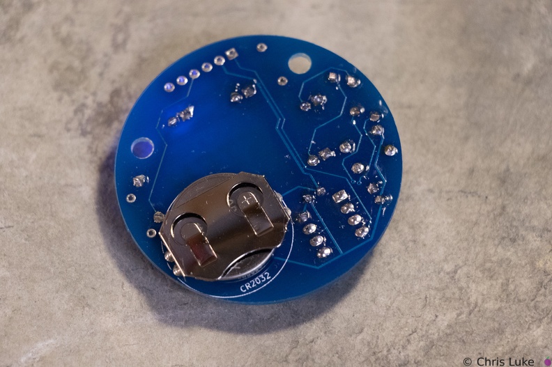
The battery holder is a simple metal cage that solders to the underside of the board.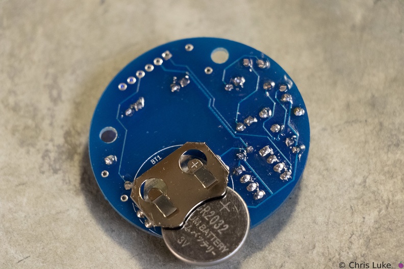 Stockton STEM Badge battery
Note the orientation of the battery. The "+" side contacts the battery holder.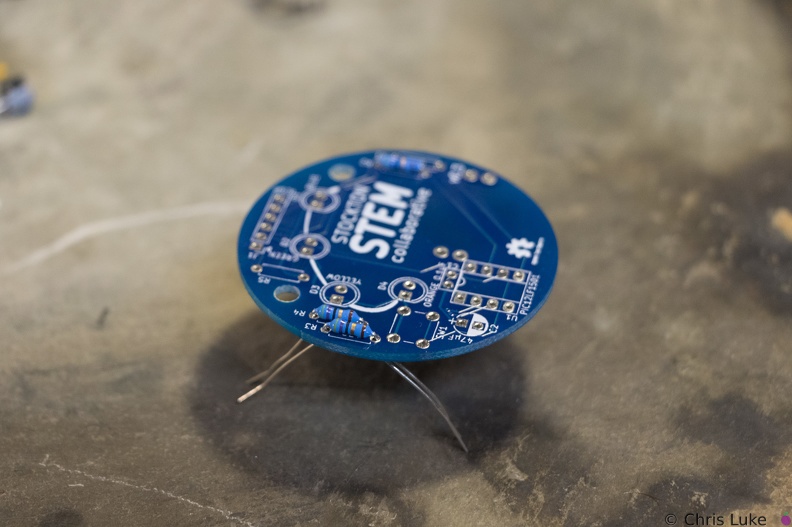 Stockton STEM Badge resistor legs
The legs are then carefully bent to about 45 degrees to hold the resistor in place for soldering.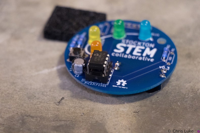 Stockton STEM Badge IC
The IC pins need to be straight and line up with their receptacles in the socket.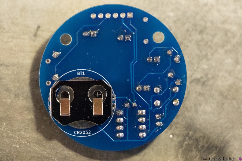 Stockton STEM Badge battery
Note the orientation of the holder; reversing it will make it difficult to insert the battery later.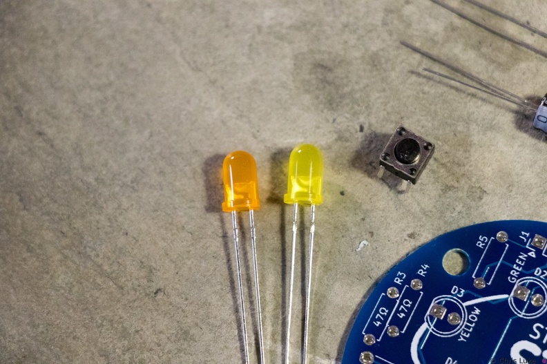 Stockton STEM Badge LEDs and button
Orange and yellow LEDS. The pushbutton switch allows a person to control the badge.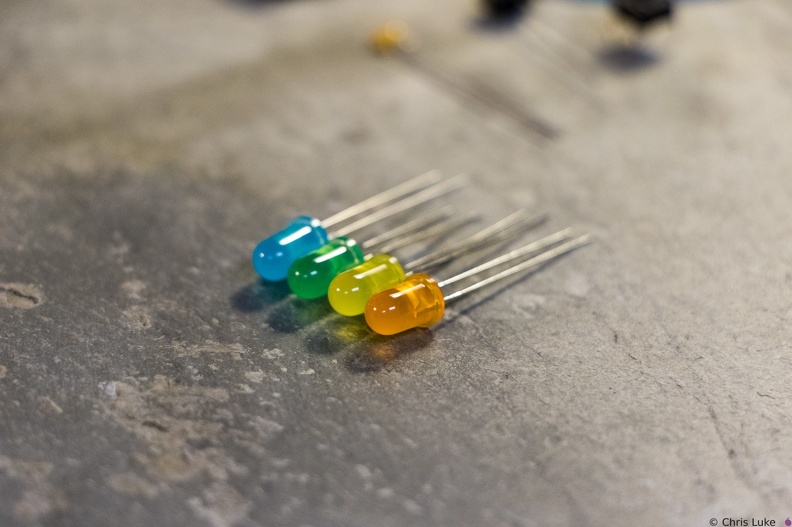 Stockton STEM Badge LEDs
 Stockton STEM Badge battery
The battery should sit snugly under the holder.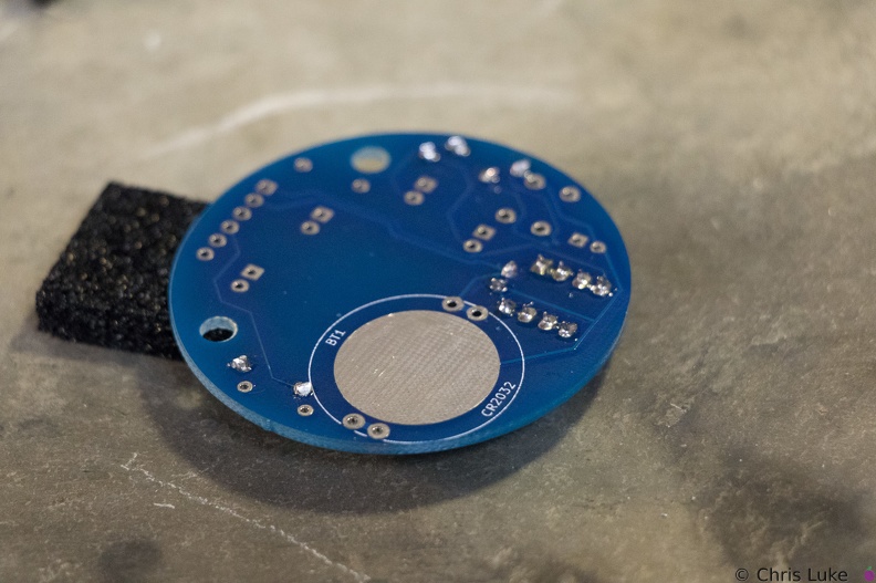 Stockton STEM Badge IC socket
Soldering one leg first and checking that the socket is flat against the board avoids a simple mistake. If it is not flat, or otherwise misaligned simply re-heating the leg will help correct the issue. Once orientation and alignment is verified, solder the remaining legs. Sometimes a small shim, such as the black foam here, can help keep the board level and simplifies the task.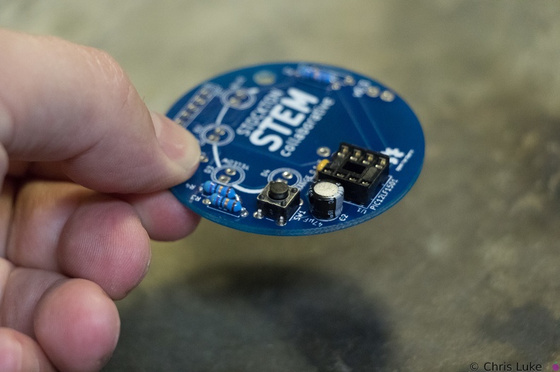 Stockton STEM Badge button
The push-button switch will fit two ways. Orientation does not matter.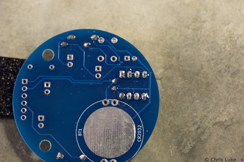 Stockton STEM Badge IC socket
Soldered legs.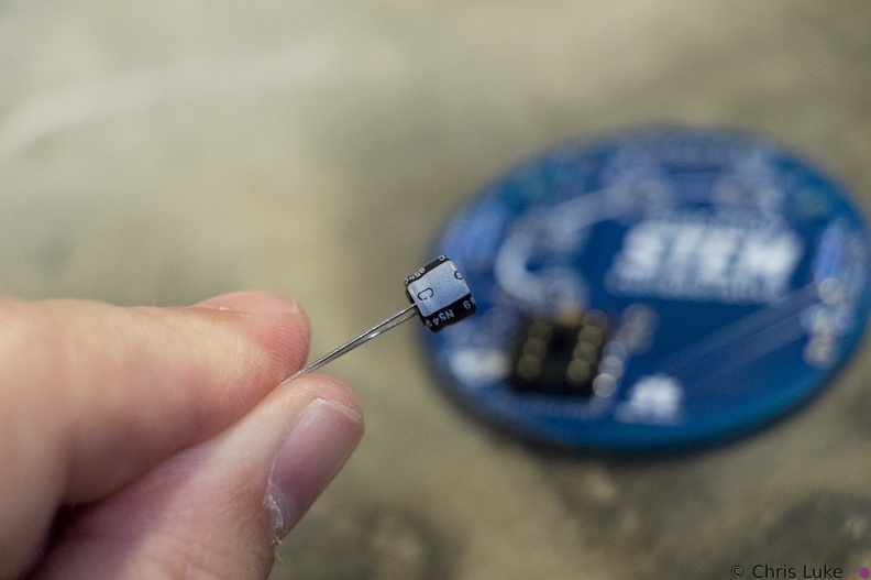 Stockton STEM Badge electrolytic capacitor
Electrolytic capacitors are polarity sensitive; note the "-" symbol on one side of the capacitor package. These capacitors typically have a larger capacity than their ceramic counterparts and are used for bulk storage; this one is used to assist the battery when the LEDs turn on. This is necessary because button cell batteries are not designed to provide as much power as the LEDs can demand.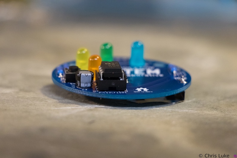 Stockton STEM Badge IC
Once pushed all the way in, the IC may sit above the socket, but it will be parallel to it.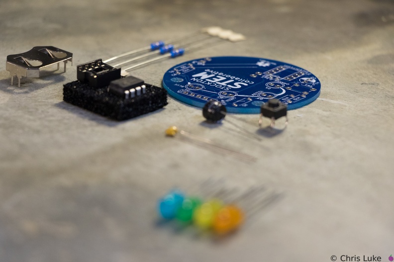 Stockton STEM Badge components
 Stockton STEM Badge IC and socket
The chip, an integrated circuit, or IC, must also be used the correct way round. Both the chip and its socket have a notch at one end to identify its orientation.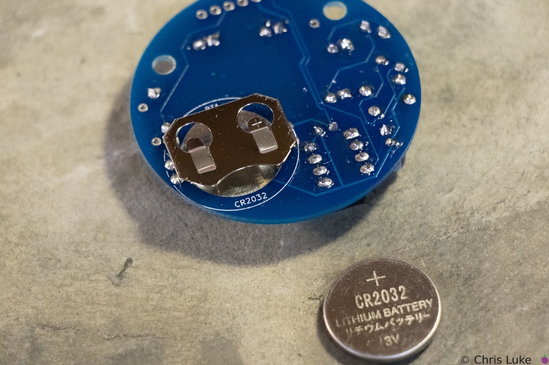 Stockton STEM Badge battery
The battery is a typical CR2032 button cell. Notice which side the "+" is on.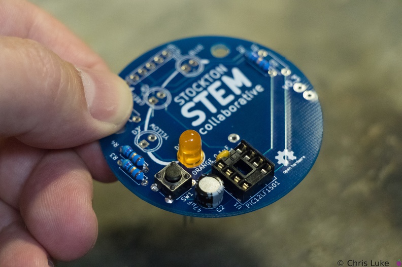 Stockton STEM Badge LEDs
The footprint for the LEDs also shows a flat edge; orientation of the LEDs needs to match that of the board.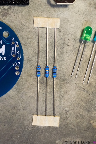 Stockton STEM Badge resistors
These are 47 ohm resistors; they limit the current supplied to the orange, yellow and green LEDs. The blue LED does not require one.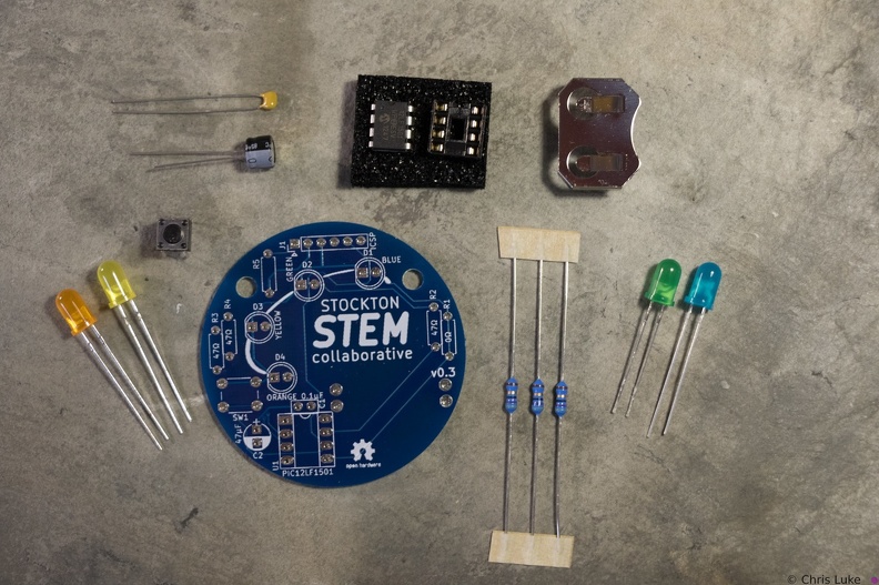 Stockton STEM Badge components
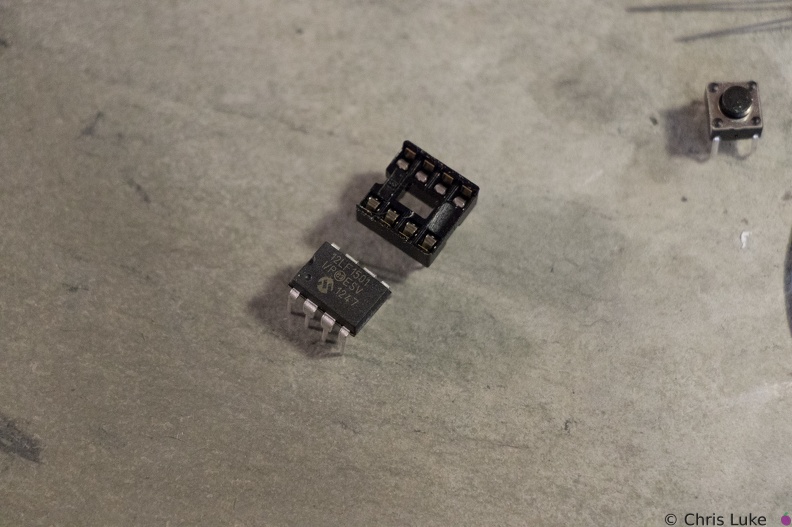
The badge consists of a handful of electronic components. Components R1, R5 and J1 are not normally populated.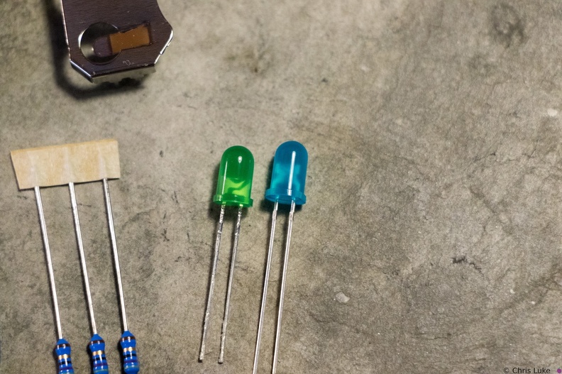 Stockton STEM Badge LEDs
Green and blue LEDs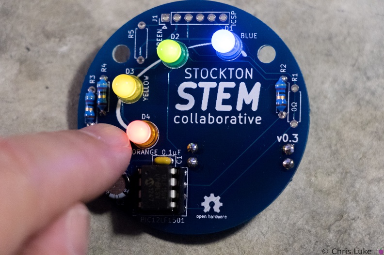 Stockton STEM Badge completed
Press the button to start the lights!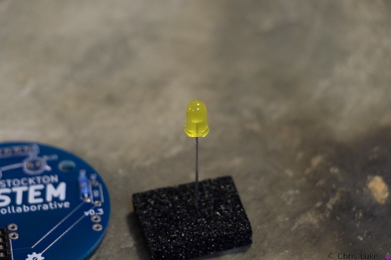 Stockton STEM Badge LEDs
While all components can be destroyed with an excess of heat during soldering, LEDs are especially susceptible to this.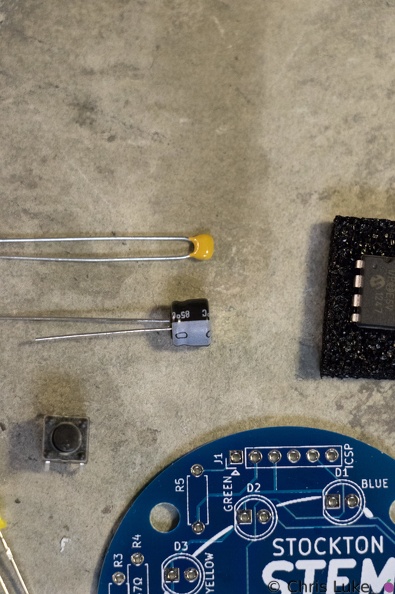 Stockton STEM Badge capacitors
The capacitors smooth the power on the badge. The top capacitor, is not polarity sensitive; that is, it can be used either way round. The other capacitor must be used only the correct way round; the case has a "-" symbol printed on it.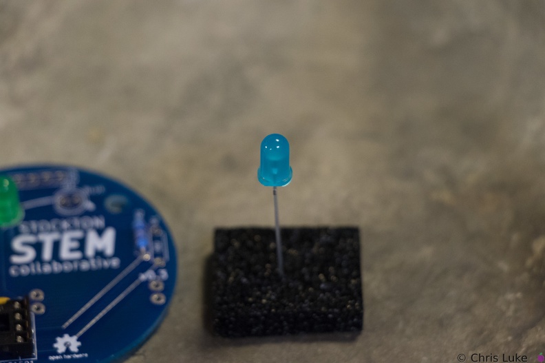 Stockton STEM Badge LEDs
The case of an LED can crack if the legs are bent too close to it; even after placing the LED on the board, only bend the legs slightly to hold it in place.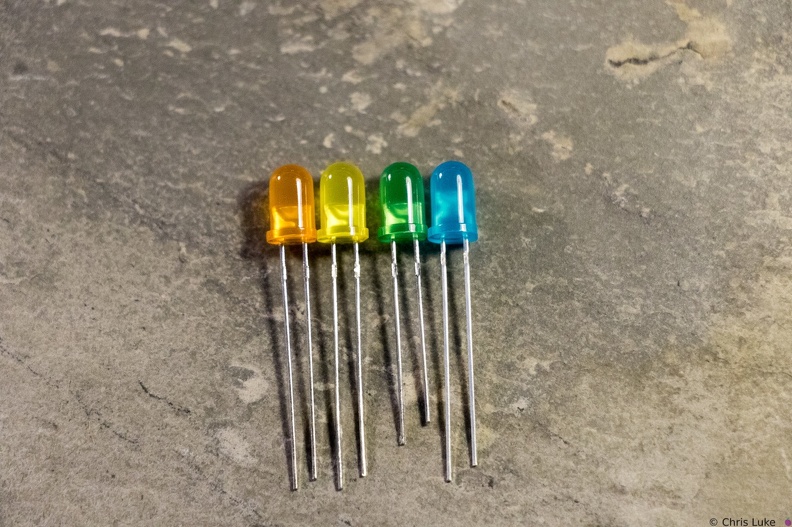 Stockton STEM Badge LEDs
Notice how the LEDs typically have one leg longer than the other; this is called the "anode". The colored case also has one flat side, opposite the longer leg; the leg on this side is called the "cathode". Also, note the distinctive shape of what is inside the colored case; this can also be used to help determine its orientation. The gap at the top of the metal surface is always on the anode side. LEDs can only be used the right way round so determining orientation is important.