
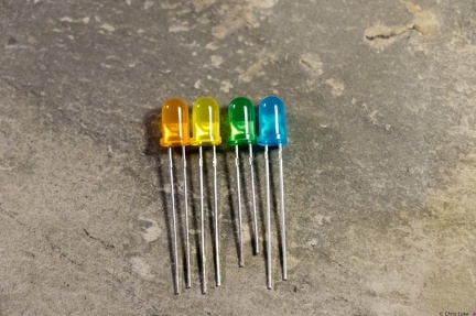
 (60506) Stockton STEM Badge LEDs
 (56679) Stockton STEM Badge LEDs
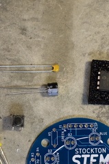 (56054) Stockton STEM Badge capacitors
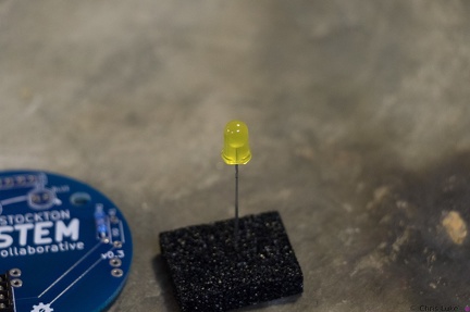 (55569) Stockton STEM Badge LEDs
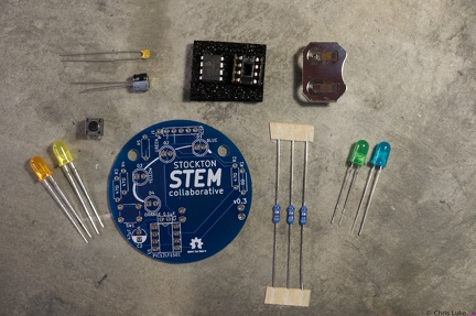 (55155) Stockton STEM Badge components
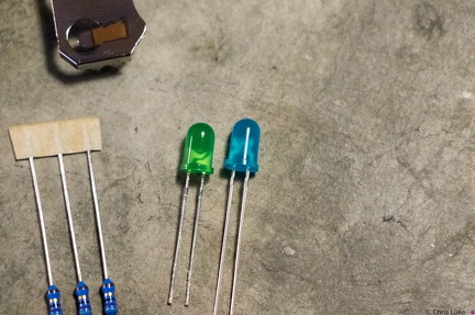 (53458) Stockton STEM Badge LEDs
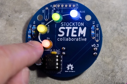 (52650) Stockton STEM Badge completed
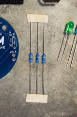 (52314) Stockton STEM Badge resistors
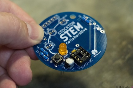 (49746) Stockton STEM Badge LEDs
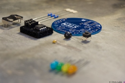 (48740) Stockton STEM Badge components
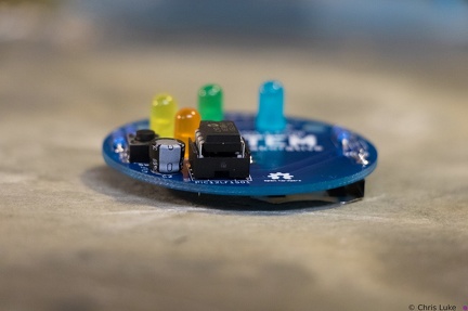 (48609) Stockton STEM Badge IC
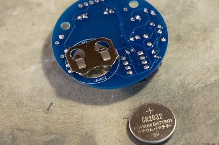 (48544) Stockton STEM Badge battery
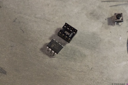 (48498) Stockton STEM Badge IC and socket
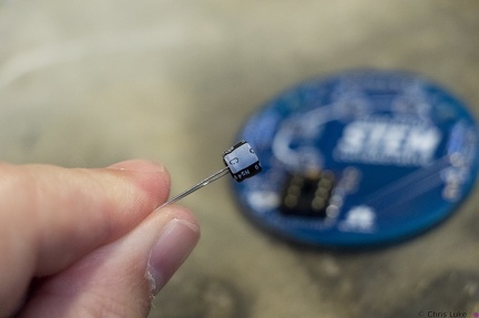 (47912) Stockton STEM Badge electrolytic capacitor
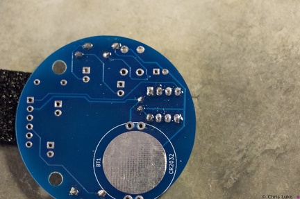 (46886) Stockton STEM Badge IC socket