« Saturday

- 100 1495
- 127 2718
- 100 1494
- 100 1493
- 127 2717
- 100 1492
- 127 2716
- 100 1491
- 127 2715
- 127 2714
- 127 2713
- 100 1490
- 127 2712
- 127 2711
- 127 2710
- 127 2709
- 127 2708
- 127 2707
- 100 1489
- 100 1488
- 100 1487
- 100 1486
- 127 2706
- 100 1485
- 100 1484
- 100 1483
- 100 1482
- 127 2705
- 127 2704
- 100 1481
- 127 2703
- 100 1480
- 100 1479
- 127 2702
- 127 2701
- 126 2700
- 126 2699
- 126 2698
- 126 2697
- 126 2696
- 126 2695
- 126 2694
- 126 2693
- 126 2692
- 126 2691
- 126 2690
- 126 2689
- 126 2688
- 126 2687
- 126 2686
- 126 2685
- 126 2684
- 126 2683
- 126 2682
- 126 2681
- 126 2680
- 126 2679
- 126 2678
- 126 2677
- 126 2676
- 126 2675
- 126 2674
- 126 2673
- 126 2672
- 126 2671
- 126 2670
- 126 2669
- 126 2668
- 126 2667
- 126 2666
- 126 2665
- 126 2664
- 126 2663
- 126 2662
- 126 2661
- 126 2660
- 126 2660
- 126 2659
- 126 2658
- 126 2657
- 126 2656
- 126 2655
- 126 2654
- 126 2653
- 126 2652
- 126 2651
- 126 2649
- 126 2648
- 126 2648
- 126 2647
- 126 2647
- 126 2646
- 126 2645
- 126 2644
- 126 2643
- 126 2642
- 126 2641
- 126 2640
- 126 2639
- 126 2638
- 126 2637
- 126 2636
- 126 2635
- 126 2634
- 126 2633
- 126 2632
- 126 2631
- 126 2630
- 126 2629
- 126 2628
- 126 2627
- 126 2626
- 126 2625
- 126 2624
- 126 2623
- 126 2622
- 126 2621
- 126 2620
- 126 2619
- 126 2618
- 126 2617
- 126 2616
- 123 2342
- 123 2341
- 123 2340
- 123 2339
- 123 2338
- 123 2337
- 123 2336
- 123 2335
- 123 2335
- 123 2334
- 123 2333
- 123 2332
- 123 2331
- 123 2330
- 123 2329
- 123 2328
- 123 2327
- 123 2326
- 123 2325
- 123 2324
- 123 2323
- 123 2322
- 123 2321
- 123 2320
- 123 2319
- 123 2318
- 123 2317
- 123 2316
- 123 2315
- 123 2314
- 123 2313
- 123 2312
- 123 2311
- 123 2310
- 123 2309
- 123 2308
- 123 2307
- 123 2306
- 123 2305
- 123 2304
- 123 2303
- 123 2302
- 123 2301
- 122 2300
- 122 2299
- 122 2298
- 122 2297
- 122 2296
- 122 2295
- 122 2294
- 122 2293
- 122 2292
- 122 2291
- 122 2290
- 122 2289
- 122 2288
- 122 2287
- 122 2286
- 122 2285
- 122 2284
- 114 1498
- 114 1497
- 114 1496
- 114 1495
- 114 1494
- 114 1493
- 114 1492
- 114 1491
- 114 1490
- 114 1489
- 114 1488
- 114 1487
- 114 1486
- 105 0567
- 105 0566
- 105 0563
- 105 0562
- 105 0561
- 105 0560
- 105 0559
- 105 0558
- 105 0557
- 105 0556
- 105 0555
- 105 0554
- 105 0553
- 105 0552
- 105 0551
- 105 0550
- 105 0549
- 105 0548
- 105 0547
- 105 0546
- 105 0545
- 105 0544
- 105 0543
- 105 0542
- 105 0541
- 105 0540
- 105 0539
- 105 0538
- 105 0537
- 105 0536
- 105 0535
- 105 0534
- 105 0533
- 105 0532
- 105 0531
- 105 0530
- 105 0529
- 105 0528
- 105 0527
- 105 0526
- 105 0525
- 105 0524
- 105 0523
- 105 0522
- 105 0521
- 105 0520
- 105 0519
- 105 0518
- 105 0517
- 105 0516
- 105 0515
- 105 0514
- 105 0513
- 105 0512
- 105 0511
- 105 0510
- 105 0509
- 105 0508
- 105 0507
- 105 0506
- 105 0505
- 105 0504
- 105 0503
- 105 0502
- 105 0501
- 104 0500
- 104 0499
- 104 0498
- 104 0497
- 104 0496
- 104 0495
- 104 0494
- 104 0493
- 104 0492
- 104 0491
- 104 0490
- 104 0489
- 104 0487
- 104 0486
- 104 0485
- 104 0484
- 104 0483
- 104 0482
- 104 0481
- 104 0480
- 104 0479
- 104 0478
- 104 0477
- 104 0476
- 104 0475
- 104 0474
- 104 0473
- 104 0472
- 104 0471
- 104 0470
- 104 0469
- 104 0467
- 104 0466
- 104 0465
- 104 0464
- 104 0463
- 104 0462
- 104 0461
- 104 0460
- 104 0458
- 104 0456
- 104 0455
- 104 0450
- 104 0449
- 104 0448
- 104 0447
- 104 0446
- 104 0445
- 104 0444
- b0030
Merlin [4/4] - b0029
Merlin [3/4] - b0028
Merlin [2/4] - b0027
Merlin [1/4] - b0026
Dartmouth Street - b0025
Air Canada [3/3] - b0024
Air Canada [2/3] - b0023
Air Canada [1/3] - b0022
A plane - b0021
The sky - b0020
Bird in a tree [2/2] ...it's in there somewhere - b0019
Bird in a tree [1/2] Can you spot the bird? - b0018
A bird Might be a goose - b0017
Tigger [2/2] - b0016
Tigger [1/2] - b0014
Wasp [2/2] - b0013
Wasp [1/2] - b0012
Tulips - b0011
Pansies [2/2] - b0010
Pansies [1/2] - b0008
Heart-somethingorothers [4/4] - b0007
Heart-somethingorothers [3/4] - b0006
Heart-somethingorothers [2/4] - b0005
Heart-somethingorothers [1/4] - b0004
Dartmouth Strete [4/4] - b0003
Dartmouth Street [3/4] - b0002
Dartmouth Street [2/4] - b0001
Dartmouth Street [1/4] - 100 0042
Merlin - 100 0041
Merlin - 100 0040
Merlin - IMG 0675
- IMG 0674
- IMG 0673
- IMG 0672
- IMG 0671
- IMG 0670
- IMG 0669
- IMG 0668
- IMG 0667
- IMG 0666
- IMG 0665
- IMG 0664
- IMG 0663
- IMG 0662
- IMG 0661
- IMG 0660
- IMG 0659
- IMG 0658
- IMG 0657
- IMG 0656
- IMG 0655
- IMG 0654
- IMG 0653
- IMG 0652
- IMG 0651
- IMG 0650
- IMG 0649
- IMG 0648
- IMG 0647
- IMG 0646
- IMG 0645
- DSC01311
- DSC01310
- DSC01309
- DSC01308
- DSC01307
- DSC01306
- DSC01305
- DSC01304
- DSC01303
- DSC01302
- P0000078
- P0000077
- P0000073
- P0000072
- P0000071
- P0000070
- P0000069
- P0000068
- P0000067
- P0000066
- P0000065
- P0000064
- P0000063
- P0000062
- P0000061
- DSC00605
- DSC00600
- DSC00599
- DSC00598
- DSC00597
- DSC00596
- DSC00595
- DSC00567
- DSC00566
- DSC00565
- DSC00563
- P0000047
- P0000046
- P0000045
- P0000039
- P0000038
- P0000037
- P0000036
- P0000035
- P0000034
- DSC00528
- DSC00527
- DSC00526
- DSC00525
- DSC00524
- DSC00523
- DSC00522
- DSC00521
- DSC00520
- DSC00519
- DSC00516
- DSC00515
- DSC00514
- DSC00513
- DSC00512
- DSC00511
- DSC00510
- DSC00508
- DSC00506
- DSC00505
- DSC00503
- DSC00502
- DSC00501
- DSC00500
- DSC00499
- DSC00498
Lyn and pre-wedding drinks - DSC00403
- DSC00402
- DSC00291
- DSC00210
The Flying Scotsman 2002-04-28 The Flying Scotsman up close with some plaster simulating the effects of rocks/debris between the two sets of track. The plaster will, if kept, eventually be coloured. - DSC00208
The Table 2002-04-28 The current state of the table. The foliage in the previous two pictures is centre right. The white splotches are experiments with two types of plaster, partly to hold the track in place (and level) and partly for scenic effect. - DSC00207
The first scenery #2 2002-04-28 More of that foliage. - DSC00206
The first scenery 2002-04-28 The first area of scenery is started. Here we have some grass and bushes. - DSC00152
A stationary decoder This is an example of the decoder used to control the points/turnouts. I wrote the switch address of each port on the connector for diagnostics sake. - DSC00151
The power management unit This is a Digitrax PM-4 power controller. On this layout, all the outputs are used for short circuit detection. - DSC00150
The Digitrax controller This is the controller of this layout, a Digitrax DCS-100 DCC controller. - DSC00148
The Table 2002-02-24 An update - two loops of track, a reversing double "wye" in the centre with the points/turnouts in the process of being wired. - DSC00135
Under the Table 2002-02-17 An example of the structure of the wooden frame. Very simple, sturdy enough. - DSC00133
The Table #2 2002-02-17 - DSC00131
The Table 2002-02-17 This is the table, a simple wooden frame with regular domestic insulation styrofoam as a surface. Here, it has been primered with Glidden "Aquacrylic Primer Ultra-Hide Gripper".  dsc00033
 dsc00030
 dsc00024
 dsc00023
 dsc00022
 dsc00021
 dsc00020
 dsc00019
 dsc00018
 dsc00017
 dsc00016
 dsc00015
 dsc00014
 dsc00013
 dsc00012
 dsc00011
 dsc00010
 dsc00009
 dsc00008
 dsc00007
 dsc00006
 dsc00005
 dsc00004
 dsc00003
 dsc00002
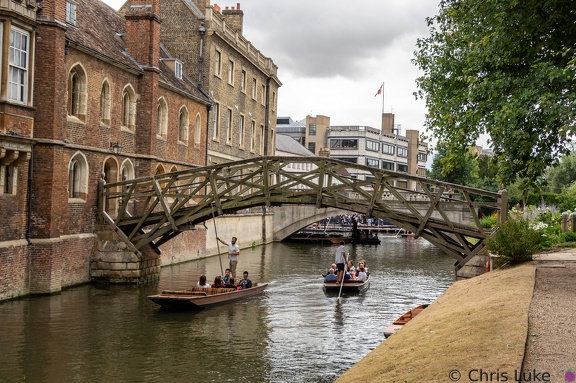
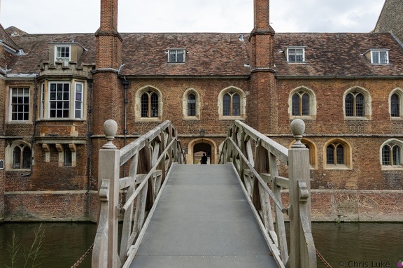 Mathematical Bridge
 3C2A6610
 3C2A7283
 3C2A6607
 3C2A7395
 3C2A6614
 3C2A6606