
 142 4269
 142 4265
 142 4266
 142 4267
 142 4263
 142 4264
 142 4261
 142 4262
 142 4260
 142 4259
 142 4258
 142 4257
 142 4256
 142 4255
 142 4254
 142 4253
 142 4252
 142 4251
 142 4250
 142 4249
 142 4248
 142 4247
 142 4246
 142 4245
 142 4244
 142 4242
 142 4243
 142 4239
 142 4240
 142 4241
 142 4236
 142 4237
 142 4238
 142 4235
 142 4232
 142 4233
 142 4234
 142 4231
 142 4229
 142 4230
 142 4226
 142 4227
 142 4228
 142 4223
 142 4224
 142 4225
 142 4222
 142 4221
 142 4220
 142 4219
 142 4218
 142 4217
 142 4216
 142 4215
 142 4214
 142 4213
 142 4212
 142 4211
 142 4210
 142 4209
 142 4208
 142 4207
 142 4206
 142 4205
 142 4204
 142 4203
 142 4202
 142 4201
 141 4200
 141 4199
 140 4033
 140 4033 crop
 140 4032
 140 4031
 140 4030
 140 4029
 140 4022
 140 4021
 140 4007
 140 4006
 140 4005
 140 4002
 119 1939
 119 1937
 119 1933
 115 1505
 115 1503
 115 1502
 114 1500
 114 1499
 114 1496
 114 1495
 114 1494
 114 1493
 114 1492
 114 1491
 114 1490
 114 1489
 114 1488
 114 1487
 114 1486
 DSC00635
 DSC00634
 DSC00632
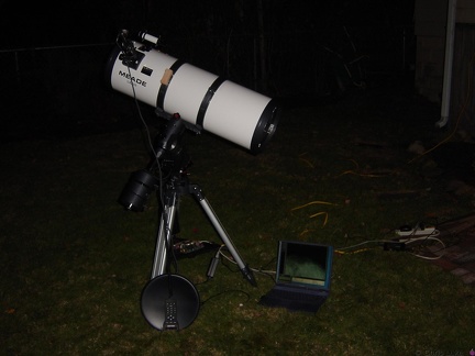 DSC00631
 DSC00629
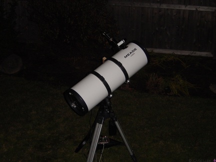 DSC00628
 DSC00627
 DSC00626
 DSC00625
 DSC00623
 DSC00620
 DSC00618
 DSC00608
 DSC00558
 DSC00553
 DSC00552
 DSC00551
 DSC00545
 DSC00543
 DSC00541
 DSC00449
 DSC00447
 DSC00337
 DSC00336
 DSC00335
 DSC00334
 DSC00332
 DSC00331
 DSC00329
 DSC00327
 DSC00326
 DSC00310
 DSC00309
 DSC00308
 DSC00307
 DSC00306
 DSC00305
 Meade LDX55 10inch Schidt-Newtonian
 Merlin
 DSC00199
 DSC00198